Sunday, February 14, 2021

Ceiling Projection of Blood Glucose Readings

 a.k.a. MQTT-RF Bridge for Ceiling-Projecting Alarm Clock Temperature

By Greg J. Badros <badros@gmail.com>
First draft 2020–03–29; last updated 2020–04–08; moved to blogger 2021-02-14

Update: If you or someone you love has diabetes, checkout out Gluroo! It's an iOS and Android mobile app that makes managing diabetes as easy as messaging.

Motivation

In February 2020, my son was diagnosed with Type 1 Diabetes. Within 4 days we had him wearing a Dexcom G6 Continuous Glucose Monitor (CGM). My wife and I each follow his CGM readings 24/7, but at night time, our primary user interface to information is a ceiling projection alarm clock. I decided to find a way to project our son’s real-time blood glucose readings unobtrusively on the ceiling of our bedroom.

First approach — Build a simple ceiling projector

At first I tried to find a ceiling projection multi-segment LCD component of some kind. Though I was hopeful, I soon became discouraged and was unable to find something easy to use in a project. I found various tutorials about making a simple projector, but the part list and the required experimentation around brightness, etc., and having to package it up to be something I’d be willing to put on the nightstand made for another challenge and would add to the cost and complexity.

Second approach — Use a Ceiling-Projecting Alarm Clock

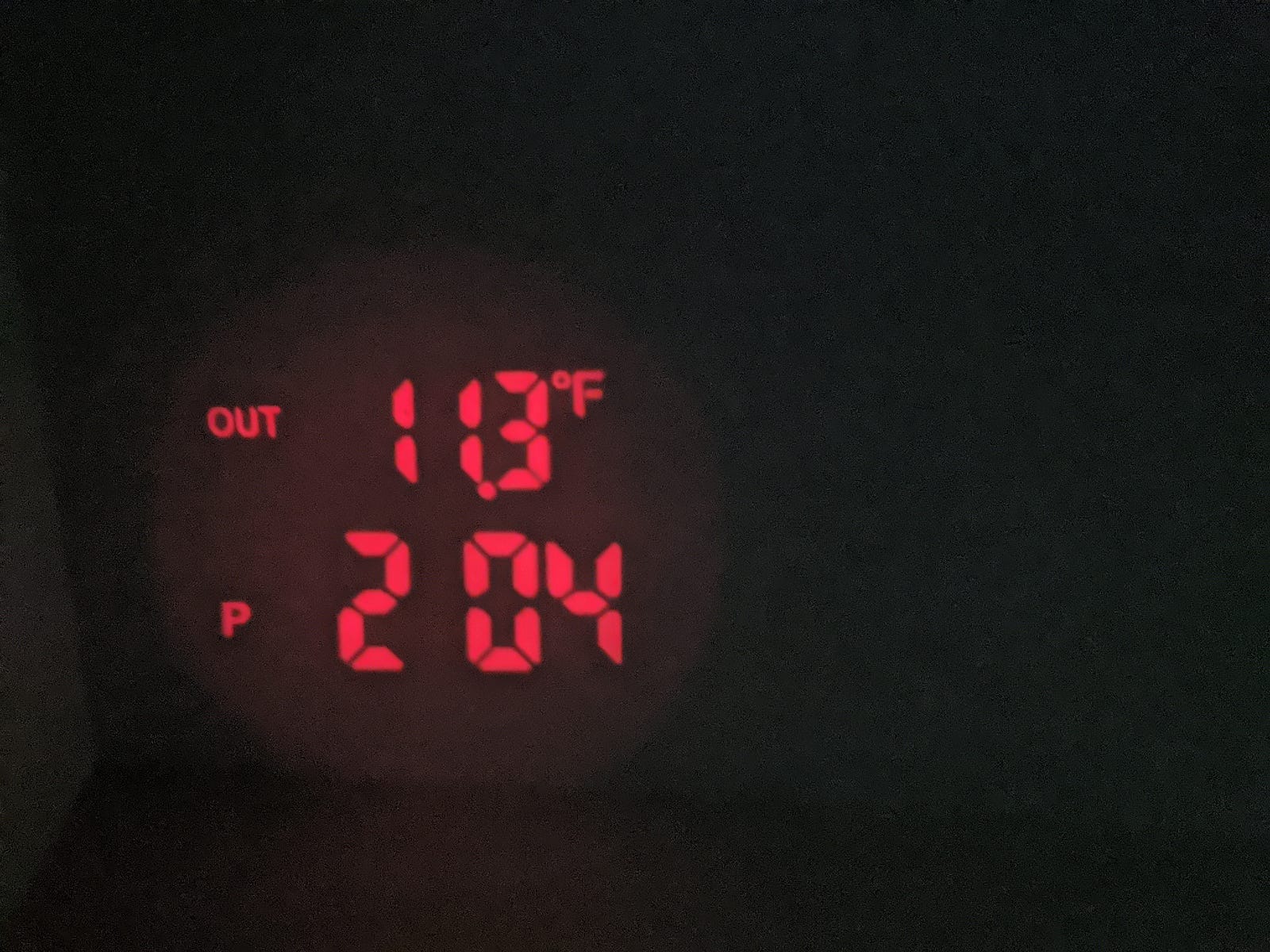
After becoming more pessimistic on the first idea, I had an insight that I could re-use an existing Ceiling-Projecting Alarm Clock and just connect in to the display or replace the display with my logic. Then I realized it was even easier than that: many ceiling-projecting alarm clocks have the ability to display a temperature from a remote module that is meant to sense the outdoor temperature. If I could reverse-engineer that outdoor-thermometer + temperature transmitter, I could transmit whatever number I was as the temperature and the ceiling projecting alarm clock would show that number of interest on the ceiling. So “all” I had to do was find a ceiling-projecting alarm clock that had three digits of temperature (e.g., 24.3 degC), reverse-engineer the outdoor thermometer module and protocol, and create a new transmitter to send a different “temperature” to the alarm clock. Here’s the end result:

The “Outside” temperature of 11.3 really means BGL of 113 coming from NightScout

Selecting the Alarm Clock

I already owned and like a circa 2005 Oregon Scientific projection clock (Model BAR338PA), but the outdoor temperature sensor/transmitter had died long ago. I searched for a replacement with no luck but found that any of models THC138, THR138, RT918 were supposedly compatible with our projection clock. I’d still love to reverse engineer those transmitters so it’d work with that clock, but for the immediate term, I needed another projection clock.

After a quick look through options on Amazon, I decided to try the Smartro Time & Temperature Projection Alarm Clock — it’s pretty basic, but has a small footprint, displays temperatures with 3 digits in equal size (on the projected view) and has a separate transmitter. I bought one to try.

Reverse Engineering the RF Protocol

I’d previously identified URH (Universal Radio Hacker) as a software tool to help in reverse engineering, and from its device compatibility list, chose the tiny and inexpensive NooElec NESDR Nano2+ software-defined-radio (SDR) receiver to listen in to the RF transmissions.

I made a couple of assumptions before learning how to use URH:

  1. The projection clock devices are made in China, so I suspected that the temperature would be transmitted in Celsius/Centigrade (not Fahrenheit).
  2. These devices are inexpensive so I suspected that they’d probably send the temperatures as an integer with the decimal point shifted and not bother with floating point representations. E.g., 23.9 degC will be sent as the integer 239.
  3. From the user manual and FCC registration of the device, it was using the common 433.92MHz frequency for radio communications.

So I fired up URH with the SDR in the USB port and started the spectrum analyzer looking at (and listening to using CubicSDR which the Nooelec device suggested — it has a good spectrum analyzer that lets you play through your speakers the “heard” RF signals) around 433.9MHz. Sure enough, I saw the RF antenna receive a blurt of data every 55 seconds or so at 433.92MHz. Just after each transmission, I saw the clock update the displayed outdoor temperature. The transmissions stopped when I removed the batteries to the transmitter, so I was confident I was seeing the right signal, and there were three bursts immediately after inserting the batteries, providing further confirmation.

The raw RF signal looked like this in URH when the temperature was 25.8 degC:

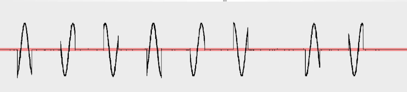
You can clearly see a modulated sine carrier wave, and it’s also clear that it’s amplitude (not frequency) modulation — technically this is called OOK (On-Off Keying) — so I applied URH’s ASK demodulation and got a waveform showing a sequence of bits corresponding to the RF chatter. I used URH’s “autodetect parameters” to help find the red/green 0/1 split point, and the time between peaks of 500 microseconds:

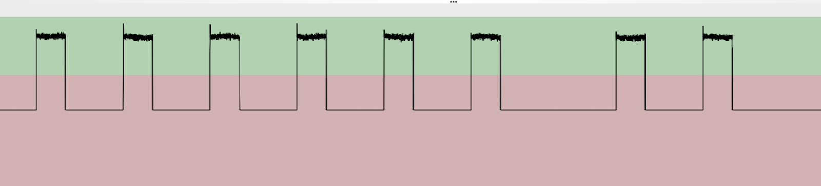
From this URH gives me the following bits:

10010010010010010000100100001000010010010010010010010000100100100100100100100001001000010000100001000010000100001001000010000100001000010000101000000001001001001001001000010010000100001001001001001001001000010010010010010010…

It’s immediately obvious that there are lots more 0s in this representation than 1s, thus suggesting that these aren’t the logically-important bits in the transmission and that there’s some other decoding to be done. At this point I recorded another handful of different transmissions at different temperatures. In particular, I put the transmitter in the freezer for 15 minutes to get a much different temperature reading. Here are the bits sent for 2.4 degC:

1001001001001001000010010000100001001001001001001001001001001001000010000100100100100001000010000100001001001001000010000100100100001010000000010010010010010010000100100001000010010010010010010010010010010010000100001001001…

And then I converted these two temperatures to binary using the assumptions I made upfront:

25.8 degC = 258 = 0b100000010

2.4 degC = 24 = 0b11000

I did those conversions to know what the binary sequence was that I was looking for in each of the two demodulated sequences of bits (presumably after another decoding step). (I had 7–8 more transmission waveforms at other temperatures but I really focused on just those two to keep the scale manageable.)

My first idea for further decoding of these raw transmitted bits was based on grouping them into triplets of 3 bits. I did a histogram after splitting these up into 3 bits and got:

Count: Pattern
152: 010
148: 001
147: 100
126: 000
4: 101

On the one hand, this was encouraging to see a relatively even split among 010, 001, and 100, with 000 (quiet on the RF) being an outlier, the 4 occurrences of 101 were weird and given the proximity of the transmitter to the snooping antenna, I discounted the possibility they were errors or noise. I also wasn’t quite clear how to think about this since one has to expect the RF communication would be designed to be robust against chopping off the beginning or end of the communication and thinking about the encoding in terms of % 3 = 0 offsets from some “start” position seemed fragile. But that’s where I quit for the day.

The next day I decided to go back to the demodulated wave form and look at it some more. That’s when I had my key insight: the peaks were just separating two differently-lengthed periods of quiet: either 1000 microseconds (1ms or 2 bits) or 2000 microseconds (2ms or 4 bits). Maybe, I thought, interpreting the shorter quiet periods as “0” and the longer ones as “1” would result in a higher-level representation of the intended transmission. I.e., in the bit sequence, “00” between two “1”s is a “0” and “0000” between two “1”s is a “1”. I wrote a quick perl script to do that conversion and got the below for 25.8 degC:

RAW:
10010010010010010000100100001000010010010010010010010000100100100100100100100001001000010000100001000010000100001001000010000100001000010000101000000001

(bold marks “00”s which are interpreted as one “0”; italics “0000”s are interpreted as one “1”)

00000101 1000000100 00001011111101111110..

And I bolded the binary for 258 (remember 25.8 degC) in the above decoding — it showed up! I repeated on the other readings and each time I found the temperature’s binary representation inside the decoded RF transmission. I did some further experimentation to confirm that negative temperatures are, as you’d guess, encoded with 2s complement. And the signal repeats itself about 10 times per transmission, each time separated by a 6 “0” quiet period (3ms).

Across multiple different temperature readings, the prefix to the temperature bits was consistent, but the suffix varied. The same temperature seemed to give the same suffix, but I could not decipher how to compute the suffix from the temperature, so I decided to ignore that puzzle for a bit and see if it mattered.

Next up, I needed to see if I could use my understanding of the protocol to synthesize an RF transmission that would be interpreted by the clock as coming from the temperature transmitter.

Transmitting Reverse-Engineered Protocol

Next up I needed a transmitter for testing the sending of these signals. My friend recommended a YardStickOne which probably would’ve sufficed both for receiving and transmitting, but I hedge a bit and only bought a receiver at first since I wasn’t sure that I’d be able to decode the protocol and figured I might just proceed to the next step (of using a small IC transmitter and microcontroller) and skip this step of prototyping the transmission of the signal from my laptop entirely. In parallel, I ordered some Arduino-compatible 433 MHz transmitters and receivers and as it turns out, those arrived first, so I skipped the step of using the YardStickOne to test transmission entirely, and proceeded to just code up the sketch for the Particle Photon.

Designing the BGL Interface to the Transmitter

I wanted to RF transmit the BGL from a Dexcom G6, and there’s plenty of open-source code out there (e.g., NightScout) for being a Dexcom Follower to get the value from the CGM through the Internet. So I wrote a tiny script that fetches the BGL level and publishes it as a message on an MQTT bus that I already have running for my smart home. I wrapped that up as a docker container so it stays running, and that simplified my microcontroller device to only have to RF transmit MQTT messages that it receives (rather than having to do HTTPS queries — an HTTP query on Particle Photon is pretty trivial but the SSL handshake adds significant complexity to an otherwise simple sketch).

Thus, the design for the microcontroller-based component is simple: it listens to a pre-specified MQTT channel for a message that is simply and integer and it broadcasts that integer via the connected RF radio.

Building the MQTT-RF Bridge Device

My go-to microcontroller of choice is the Particle Photon and this project was no different. I used just four parts. Here’s the BOM (Bill of Materials):

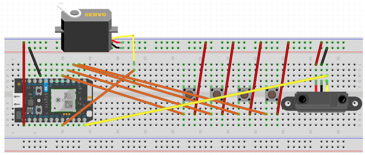
The transmitter is low power enough it can be powered by the photon itself, the connections are simple:

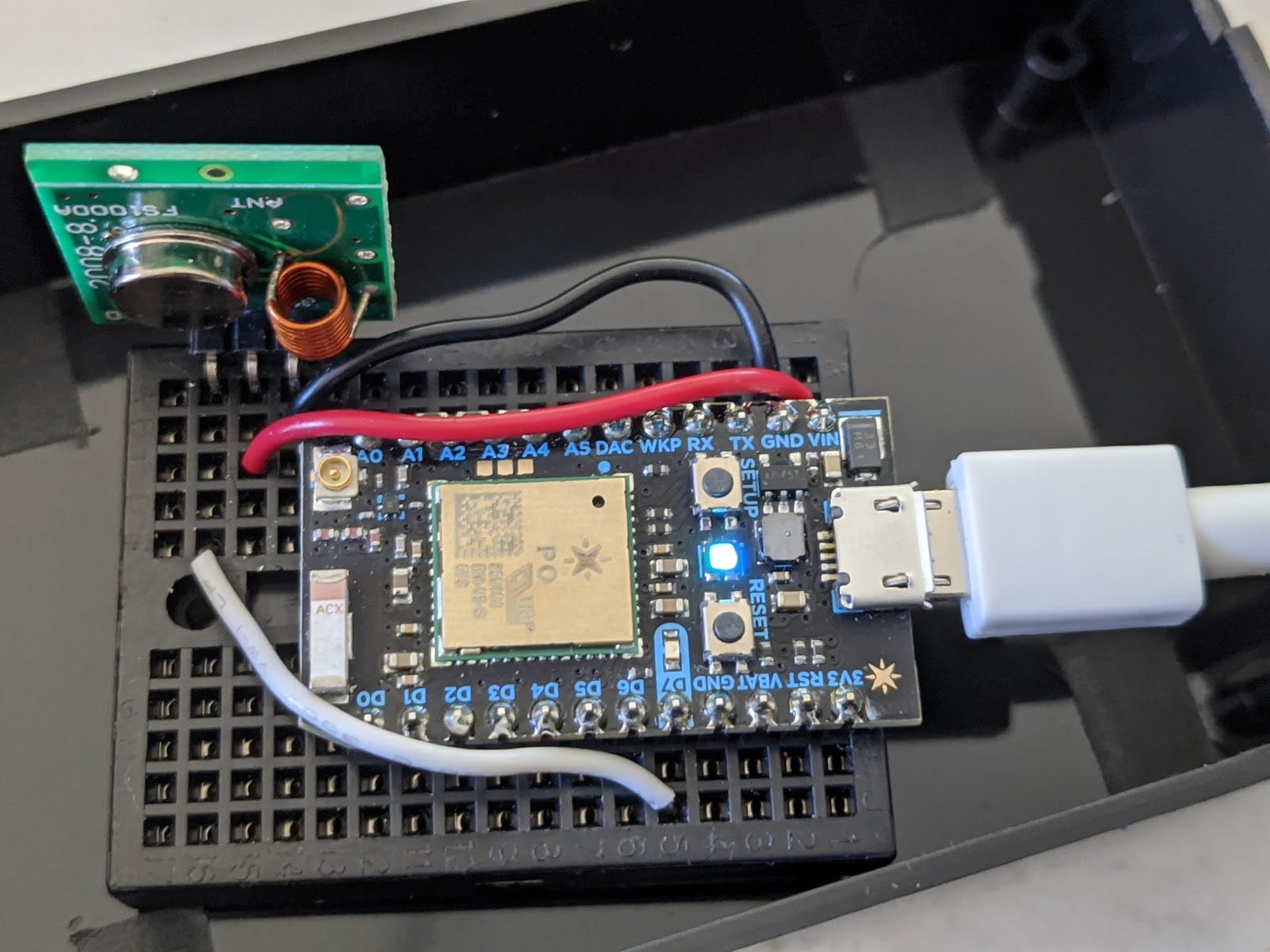
The sketch will (TODO) soon be available on github. Originally, I planned to use the RadioHead library, but it wasn’t immediately trivial to make that work with the Particle Photo microcontroller, so I decided to try just driving the RF transmitter directly by driving the D7 pin, and that worked (in the sense that I could see the transmissions on my NooElec RF snooper).

At this point, I was debugging by comparing the demodulated waveforms of the same temperature as transmitted by the stock outside thermometer transmitter vs. my homebrewed device. There were a couple of small tweaks to the analog signal — e.g., between the repetitions of the temperature with its padding, the signal is actually an exception to the short/long pause for 0/1 rule: it is low for 500 microseconds, then high for 500, then low again for 4ms. I still wasn’t sure if this would work with the clock, but making the waveforms look the same when snooped seemed likely to drive the receiver in the projection clock.

Finally, I tested with the clock and had some trouble getting consistent results. I was always able to get the transmitted reading to show up when I put the clock in “synchronize” mode (by holding the “+” button on the clock for 3 seconds), but it would stop working some time later. I spent a bunch more time believing that maybe those extra bits were checksums of some sort (but they weren’t an easy binary function and I doubted that they bothered with a lookup table to compute the checksum) or a sequence number (but they didn’t appear to be monotonically increasing.

After some further experimentation, it turns out that the projection clock is actually only listening for the radio transmission exactly every 57 seconds or so! With that realization, I updated my MQTT publishing script to publish exactly every 57 seconds. Although that worked better, the timing wasn’t reliable and really it’s a property of the the connection between the RF transmitter and the projection clock, so it’s a better design to have the RF transmitter Particle photon sketch be responsible for managing the 57 second timing itself. I reworked the sketch to remember the MQTT messages but instead of doing the RF transmission in the callback for a message, just do the RF transmission of the last-received message exactly every 57 seconds. That works reliably… done!

Improvements

It would sure be nice to know what those extra bits in the RF transmission message are for, but ultimately they don’t seem to make a difference. I also wish the projection clock only projected the outdoor temperature instead of alternating between the Inside temperature and the outside temperature. I may choose to repeat the process with a different clock radio after researching the options even more carefully.

The fact that the indoor and outdoor temperatures alternate is even worse when projecting in celsius, which is how I started using the clock: 19.7 degC is a reasonable temperature for indoors, and 197 is also a reasonable (though high) blood glucose level. Thus, I switched the code to convert the incoming MQTT message BGL to a centigrade temperature before sending the number to the clock so that it when it converts it to Fahrenheit it shows correctly. Unfortunately, this is a slightly lossy conversion: e.g., if the BGL is 128, we can tell the clock it’s -10.7 degC (12.7 degF for 127) or -10.6 degC (12.9 degF or 129) but we can’t actually get the clock to show 128. This isn’t that big of a deal in practice since a single digit difference in BGL isn’t important, but it’s a little annoying.

Source Code

See https://github.com/gjbadros/particle-photon-mqtt-rf-bridge.git

Saturday, July 23, 2016

Multi-Featured iPad Wall Mount for Home Automation

Disclaimer: I make no promises whatsoever that this does anything useful and anything you do with these instructions are your own decision.  I take no responsibility for any injuries (including death!), property damage, wasted money, wasted time or any other negative consequences from your reading or acting on this -- use at your own risk!

Overview

I describe a multi-featured iPad Wall-Mount designed for use as a home automation user interface. The mount provides power and wired networking to the tablet, digital audio extraction from the tablet, and four customizable buttons.  It also provides an auto-on feature to smartly and automatically turn on the tablet’s display when a user approaches its location and turns it off after they have left.  The mount can be built for about $200 worth of parts and requires light general electronics skill to assemble. I first built this in January of 2016 and have improved it through a half dozen iterations since then.

Problem Statement

Contemporary tablet wall mounts solve very few of the problems facing home automation user interfaces.  Among those problems are:


  • P1: Tablets rely on WiFi which is inferior to a hard-wired connection for a permanently wall-mounted tablet.
  • P2: Tablets often are used to control a separate music player instead of directly providing their digital audio output to an amplifier for use directly as a music source.
  • P3: Tablets generally have no physical customizable buttons
  • P4: Tablets manage power by turning off their display when not in use, focusing on direct user interaction with the screen to define use and do not automatically turn on when a user is about to engage with the tablet.
  • P5: Tablets require power to remain charged and functional.


Generally, most permanent tablet wall mounts only address the last of these problems, yet all are important.  My solution addresses all five of these problems using a custom 3D-printed frame, various off-the-shelf components that get hidden in the wall behind the tablet, and light general electronics skill to assemble.

Design and Key Insights

Solution #1: Support wired ethernet
Wireless networking is great for a tablet on the move, but when it’s stationary, the combination of lower reliability, wasted wireless bandwidth, and unnecessary RF interference make using a wireless connection unsatisfactory.
More recent versions of iOS support wired Ethernet networking.  You simply must use USB OTG (on-the-go) so that the iPad can work as a USB host (rather than client).  The Apple Lightning-to-USB Camera adapter is an OTG adapter for the iPad that duplicates the Lightning input (to provide power to the client device and the iPad) and provides a USB jack for devices.  The Apple USB Network Adapter plugs into that USB jack and receives an RJ45 plug connected to a network switch, and the iPad will use that Ethernet port for connectivity.


Solution #2: Extract Digital Audio
Oftentimes a home-automation tablet is used to control a separate music player such as a Sonos or Squeezebox (via iPeng or similar).  Generally, the best player interfaces are those that are native to the software outputting music directly on the phone or tablet, so it’s a shame to not be able to harness that output audio in its highest-quality digital form.


Recent versions of iOS also support external audio devices.  That same OTG USB port can be used to an audio adapter that has a variety of features.  I like the Muse USB DAC because it has an Coax and Optical Digital S/PDIF output and RCA analog outputs.  It’s then easy to use a pair of wires from a CAT6 cable to carry the electrical (not the optical) S/PDIF output back to a receiver to drive speakers or distribute the audio signal.


Solution #3: Add customizable Buttons
For issuing a quick command at a wall switch, a physical button that can be customized to do anything is hard to beat.


Arbitrary physical buttons are a favorite IoT project and are straightforward to set up once you decide how you want them to signal the action when they’re pressed.  For this mount, I simply provide a layout for four momentary switches, and wire them either a) to digital inputs of a micro-controller and program the microcontroller to make configurable HTTP requests when each button is pressed; or b) wire them directly to relays to provide dry contact inputs to a separate controller that then accepts the contact closure as a trigger for an arbitrary action in its universe.


Solution #4: Turn the Display On When a User Approaches It
If an iPad screen is dark on a conventional wall mount and a user wishes to issue a command to the currently-running app, they first must wake the tablet up by touching the screen and perform the relevant action in that app.  If the currently-running app is, for example, virtual switches for the current room’s lights or an audio play where the user might have a simple desire such as pausing or restarting music, the single extra click to wake up the tablet more than doubles the interaction time.  This is unacceptable in a high-use environment, as is leaving the display on all the time (distracting plus energy inefficient).


The foundations of my approach to this problem are: 1) An infrared distance sensor with a range of 20-150cm that reports the distance as an analog voltage; and 2) a pair of magnets -- one of which is physically moved by a servo -- that emulate an iPad cover and tickle the iPad’s magnetic sensors to turn the display on and off just like the manual covers do.  The distance sensor is connected to an analog input of a Particle photon microcontroller, and the microcontroller is coded to watch for objects under a certain distance away.  When something is close, it assumes a user has approached the tablet and triggers the servo to move one of the permanent magnets away from the home key on the iPad thus deactivating the second magnetic sensor and turns the iPad on (when both magnetic sensors on the iPad sense magnets -- like they do when the iPad’s cover is on) the iPad display goes off.


(There are several alternative possibilities to this solution that I explain in alternative designs, later.)


Solution #5: Provide Power to the Tablet
This is straightforward and I simply use a passive POE (power-over-ethernet) solution to power the powered USB hub and then plug the lightning connector that comes with the iPad into the hub and into the tablet or Lightning-to-Camera USB Adapter used for solving Problems #1 and #2.  There’s some modest trickery in ensuring that the Apple device will take the charge, but when you’re just trying to trickle-charge the iPad on the wall, many solutions suffice.


All of these solutions must, of course, be embedded in an attractive and functional mount that actually holds the iPad and the components necessary to interact with the iPad (e.g., cable management, mounting the distance sensor, servo, magnets, and buttons, etc.). I designed this part in Sketchup and 3D-printed it using Shapeways’ service.  My mount focuses on the bottom-left corner of the mount so that it fits inside of a 18cm x 10cm x 2cm bounding box which accelerates the speed of delivery from Shapeways and reduces its cost during prototyping.

Parts List (BOM) for the Wall Mount

My Custom 3D Printable iPad Mini Mount Frame
Price: ~$50 to print in strong and flexible plastic from Shapeways


Price: $39


Price: $28


Price: $20


Price: $24


Price: $17


Price: $19


(optional if you need contact-closures for the buttons - $30)


Price: $4


Price: $16


Price: $4


Price: $12 each = $24


Price: $8 for 25 (so <$1 for the two you need)


Price: $6 for 20 (so $1.20 for the four you need)


Price: $5


Thin paperclip, glue, 22 gauge solid patch wire, RCA audio cable


Sketchup Model


Front View:


Back View:


The Circuit

Using a Particle Photon microcontroller, the circuit is straightforward.  We wire D1, D2, D3, and D4 to the momentary contacts (i.e., the pushbuttons).  We wire the IR distance sensor to analog input A0. Finally, we wire the pulse output for the servo motor from analog output A4, one of the pins that supports PWM output and the servo API.  See the Breadboard and circuit views that I drew using Fritzing.

Breadboard View    

Schematic View

Assembly Instructions

After printing out the 3D model, assembly is a simple matter and takes about 30-40 minutes (probably allocated 2-3x for this the first time you try):


  1. Attach the servo bar to the top of the servo, bend a small paperclip into a right angle and attach it to the servo (see the finished prototype photos).
  2. Push the four pushbuttons through the opening in the mount and glue the bottoms of the buttons to mount.
  3. Solder the buttons to the power and D1 through D4 (note that the prototype photos only show one button soldered -- I didn’t bother connecting all 4 when I took the photo).
  4. Assemble a mini breadboard with the circuit including the Particle Photon microcontroller and connect the IR sensor and the servo wires to the breadboard.
  5. Connect the lightning port of the iPad to a digital camera adapter (use a lightning extension cable if you prefer).  Plug another lightning cable into the digital camera adapter to power the adapter (and charge the iPad Mini), plug the other end into the 4-port powered hub.
  6. Plug the digital audio USB adapter into the hub, connect the S/PDIF output of the adapter to the appropriate wires on the RJ45 screw connector.
  7. Plug the Apple USB ethernet adapter into the hub, and plug a networking ethernet cable into the RJ45 jack on the USB ethernet adapter (the other end goes in your networking router/switch).
  8. Connect the +5V and GND power wires from the RJ45 screw connector to the power connectors on the powered USB hub and also to the + and - on the breadboard.
  9. Glue the one fixed magnet into the upper/higher magnet location in the mount, put the second, moving, magnet into the lower magnet location where it can slide around and put the other end of the paperclip through the hole from the back of the mount.

Early Prototype Photos


Finished Prototype Photos and Video

Alternative Designs

In this section I explain a couple alternative approaches that I considered and either discarded or might explore further.


Turning on the iPad screen
My first design used an electromagnet that either is activated (to turn the display off) or deactivated (to turn the display on) instead of a permanent magnet moved by a servo.  The flaw with that design is that the solenoid required about 2 watts of power from behind the tablet to trigger its magnetic sensor. Drawing 2 watts in order to keep a display turned off seems unacceptable, hence the newer design using two permanent magnets and a servo.


Another alternative design worth exploring further is simply interrupting the charging current to the iPad and then reinstating it.  iPads appear to turn on their display when plugged in, so this is also an easy solution to turning the screen on.  However, the screen won’t turn off until it times out per your display settings.  This approach may work well with a short timeout for turning the display off.


Sensing a User in front of the screen
I didn’t explore the alternatives for this much in designing this iPad mount because I had some experience with different approaches from an earlier project where I designed and built a directional motion sensor for counting the number of people in a room with a single doorway for entry and exit.  

The sensor choices worthy of contemplating are: 1) Passive infrared (PIR); 2) Ultrasonic; and 3) IR Laser.  


The disadvantage of PIR is that it’s hard to tune distance and far away larger heat footprints look identical to smaller up-close heat masses.  PIR is great for its low power and completely passive nature.  Note that for Android tablets, it’s possible to configure a motion detection application that uses the (visual spectrum) front-facing camera and then uses Tasker to turn on the display.  Apple’s more limited power-user API precludes this approach.  Using simple motion detection on the camera is flawed in similar ways to PIR, but a more heavyweight facial-recognizer would likely reduce false positives (at the expense of computational and energy expense.


Ultrasonic has a number of great properties including wider visibility and accurate distance measurement, but depending on the  frequency, the sound may bother pets and more importantly, multiple uncoordinated ultrasonic sensors within earshot results in bad readings.  See the Ultrasonic Doorjamb for more of a discussion of this issue (which I only found after doing my doorjamb sensor that I ultimately switched to using IR laser).


Those shortcomings ultimately led me to use an IR laser sensor.  One downside that is rumored that I’ve not encountered is the worry that it can confuse IR receivers on electronics and interfere with IR cameras.

Next Steps

I’d love to see a consumer electronics company pick up on some of these ideas and make a powerful and flexible wall mount using these ideas.  I’m happy to be contacted by folks interested in productionizing this.


I’m still slightly partial to tablet-stands for tablets and may turn this more into a tablet-stand to place in a wired display shelf rather than mounted on the wall.


If the push buttons on the mount are not of interest or do not need to be labelled, the mount could shrink horizontally by mounting the distance sensor vertically and using a right-angle Lightning connector.  In particular, that would be easier if making a full-height frame which would allow more vertically room for the sensor.  (Thanks to Eric Badros for that observation.)

Thursday, January 7, 2016

Meet Alexa, the Amazon Echo - New Features for Home Automation

In early January 2015, I received the Amazon Echo. I'm always curious about new consumer electronics devices, and this looked to be something pretty different.  It purported to be a music player (competing with Sonos and many others, it seemed) but also announced voice recognition, natural language understanding, and interactive question answering capabilities that put it in a different category.

When the device did arrive, I was pleasantly surprised.  In particular, it's a good quality single-channel bookshelf speaker: it can pair with a bluetooth device and act as a speaker for your phone or iPad as well as play music from your personal music collection or Amazon Prime Music or several other online music catalogs.  But more importantly, it has a wicked-good array of microphones that pick up your voice commands after saying the hotword "Alexa" or "Amazon".  I'd been trying lots of microphone solutions to integrate voice into my home automation system, and back in 2010 gave up on open-air speech solutions, relenting after configuring Skype as a whole house microphone which requires speaking into a phone or iPod Touch.  The Echo microphones coupled with their voice recognition engine works beautifully from across the room even with some significant background noise.  Off the shelf, you can ask it about the weather, sports scores, to play music or a specific song, and lots more.  Everything you say shows up in a companion app on your phone that also lets you interact with some of the features via a classical small-screen user-interface.

Jump ahead a couple months and Amazon released the Echo SDK which made it possible to do integrations as extensions to the grammar Amazon provided.  Even the earliest versions of the SDK were sufficiently solid that I was able to code an integration into Homeseer/Rover in a short afternoon, so now we can say, e.g., "Alexa, ask house to turn fireplace lights on" and exactly that happens.  It understands various devices, events, and scenes given the set of sample utterances I auto-generate from metadata of my home control software.  Sidenote: I use AWS Lambda as the execution platform for the code -- I love not needing an always-running server to handle this computationally-simple and infrequently executed actions.

But lots is missing...

The Amazon Echo is already a compelling gadget, and because it's off to a great start, I realized that it could be an important component in the whole-house automation system I'm working on for a new home we're building now.   Here's my list of improvements to the hardware and software for the Echo that will make the Echo's successor be able to serve among the underpinnings of any smart home.

Whole House Audio Support

The Echo could take a play from the playbook of Sonos and enable two Echos to work as a stereo pair, or perhaps pair with a speaker-only companion that can be the second speaker in a pair.  For lots of folks, though, what would be better is simply enabling digital-audio output from the single Echo itself.  The on-board mono speaker is great for talking back to the user, but for any at-length music listening experience, you really want to use an amp or receiver with your preferred speakers.  Ideally the digital-audio would be a coax out (not optical) since the coax digital plays nicer with inexpensive baluns (gadgets on both ends that let you use the copper on a CAT5/6 cable to transmit signals other than ethernet) for a centrally-wired whole house audio system.  The Echo should still turned down the music when it hears the hotword since that's an essential feature to being able to control the music after its started.

In addition to wired digital audio-out, I'd love to see the Echo pair with other bluetooth devices as a music player (as opposed to as a speaker).  I.e., to support the music being played by the Echo to be transmitted via Bluetooth (ideally with the aptX low-latency codec) to a bluetooth receiver connected to your preferred speaker system.

An alternative to having Echo drive the music itself is to integrate Echo as a controller for SqueezeBox or Sonos music systems.  Those systems are already in place in many houses driving speakers as desired, but don't have good voice integration.  Asking "Alexa, play One by U2" (a tough sentence to parse for sure) should queue up that song on the SqueezePlayer serving the same room as the Alexa.

Echo App Improvements

The companion Echo app on the phone/tablet also needs to be improved to be competitive with the other music apps out there.  In particular, it needs to 1) start up in less than 1.5 seconds -- right now on a LG G4, I wait 10 seconds or more to do anything with the app; 2) integrate with Android Wear for pausing, volume changing, and confirmation of what you just said coupled to Undo functionality; 3) support multiple Echos including switching which one you're controlling.

I'd also like to see the Echo app have a display mode where it's reporting about what's happening on the echo in that room.  This mode would be useful for mounted tablets near each Echo for when voice control isn't sufficient or you just want to know what song is playing, pause it, change the volume, or whatever.

Even better is for the Echo to be able to pair to a tablet as its display partner to support multi-modal interfaces rather than just having the tablet (or phone) reporting its status.  For example, the voice command "Alexa, buy tickets to The Force Awakens" is best served by a continued interaction on a screen rather than reading off a list of possible venues, show times, and viewing options.  If a screen isn't available, the more tedious voice interface could continue, but by using a touch screen in collaboration with voice commands, the interaction becomes much more natural allowing a click or a response like "The first one looks good" to finalize the purchase.


Multiple Echo Support

One can easily imagine having an Echo in each room of the house, enabling music to follow you around the house (based on Bluetooth beacons or another signal identifying your location).  An important part of this is enabling micro-location awareness of each of the Echos so that they know how they relate to other devices you wish to control.  For example, in my bedroom saying "Ask house to turn the lights on" should have a different affect than in the living room: unqualified device descriptions need to use the context of the room to disambiguate.  (And fully-qualified device names should work anywhere: "Ask house to turn the master bedroom ceiling lights off" should work from anywhere in the house.)

Person Identification

Related to multiple Echos and having per-room context is having per-person context.  Minimally, certain functionality should be able to be limited to certain speakers (perhaps with an override code word when the voice is a close match but not close enough?)  For example, "Alexa, disarm the security system" should do just that but only if a recognized voice issues the command (and perhaps only if a camera near the entrance also confirms facial identification of a household member).

Voice Notifications

Another useful feature is enabling push voice notifications to an Echo.  If my garage door is open for more than 15 minutes, I have tablets in my house that are running my automation control software report "Garage door is open!"  Ideally such notifications could be pushed to any/all of the Echos in a house, and have each local Echo support do-not-disturb functionality to block or delay those notifications from a specific room.

More Hotwords

Having just two hotwords is somewhat limiting (especially since my daughter's name is Alexis -- we can't use Alexa as the hotword, and the word Amazon comes up in our daily conversation too often). It would also be great if some hotwords could tie directly into a skill so instead of saying "Alexa, ask house to turn lights off" one could say "House, turn lights off" where "House" replaces "Alexa, ask house".  Probably having two or three such skill-tied hotwords would make a significant practical difference for high-use skills.  Note also that this approach sidesteps the more complex goal of extending the core grammar with developer-defined utterances -- that seems challenging to do in a scalable way across multiple third-party providers of skills.

Better Control of other Devices

There are already a handful of integrations of the Echo with other device ecosystems (e.g., with SmartThingswith IFTTT), but I'd love to see the Echo just have better support natively for various IP-controllable devices like TiVos, HDTVs, etc.  SimpleControl (formerly Roomie Remote) does a fantastic job with a massive library of controllable devices (including support for IR blasters for older components), and Echo should be able to control the same class of gadgets that don't require new antennas, protocols, or additional hardware support.  If they really want to play in the smart home hub space, adding ZWave (my favorite right now), Zigbee, Weave, Bluetooth mesh, etc., support would be pretty useful.

Conclusion

I'm hopeful that the next generation Echo will have some set of these features, and certainly others from the clearly insightful forward-thinking team that came up with v1.  I can't wait!