Disclaimer: I make no promises whatsoever that this does anything useful and anything you do with these instructions are your own decision. I take no responsibility for any injuries (including death!), property damage, wasted money, wasted time or any other negative consequences from your reading or acting on this -- use at your own risk!
Overview
I describe a multi-featured iPad Wall-Mount designed for use as a home automation user interface. The mount provides power and wired networking to the tablet, digital audio extraction from the tablet, and four customizable buttons. It also provides an auto-on feature to smartly and automatically turn on the tablet’s display when a user approaches its location and turns it off after they have left. The mount can be built for about $200 worth of parts and requires light general electronics skill to assemble. I first built this in January of 2016 and have improved it through a half dozen iterations since then.
Problem Statement
Contemporary tablet wall mounts solve very few of the problems facing home automation user interfaces. Among those problems are:
- P1: Tablets rely on WiFi which is inferior to a hard-wired connection for a permanently wall-mounted tablet.
- P2: Tablets often are used to control a separate music player instead of directly providing their digital audio output to an amplifier for use directly as a music source.
- P3: Tablets generally have no physical customizable buttons
- P4: Tablets manage power by turning off their display when not in use, focusing on direct user interaction with the screen to define use and do not automatically turn on when a user is about to engage with the tablet.
- P5: Tablets require power to remain charged and functional.
Generally, most permanent tablet wall mounts only address the last of these problems, yet all are important. My solution addresses all five of these problems using a custom 3D-printed frame, various off-the-shelf components that get hidden in the wall behind the tablet, and light general electronics skill to assemble.
Design and Key Insights
Solution #1: Support wired ethernet
Wireless networking is great for a tablet on the move, but when it’s stationary, the combination of lower reliability, wasted wireless bandwidth, and unnecessary RF interference make using a wireless connection unsatisfactory.
More recent versions of iOS support wired Ethernet networking. You simply must use USB OTG (on-the-go) so that the iPad can work as a USB host (rather than client). The Apple Lightning-to-USB Camera adapter is an OTG adapter for the iPad that duplicates the Lightning input (to provide power to the client device and the iPad) and provides a USB jack for devices. The Apple USB Network Adapter plugs into that USB jack and receives an RJ45 plug connected to a network switch, and the iPad will use that Ethernet port for connectivity.
Solution #2: Extract Digital Audio
Oftentimes a home-automation tablet is used to control a separate music player such as a Sonos or Squeezebox (via iPeng or similar). Generally, the best player interfaces are those that are native to the software outputting music directly on the phone or tablet, so it’s a shame to not be able to harness that output audio in its highest-quality digital form.
Recent versions of iOS also support external audio devices. That same OTG USB port can be used to an audio adapter that has a variety of features. I like the Muse USB DAC because it has an Coax and Optical Digital S/PDIF output and RCA analog outputs. It’s then easy to use a pair of wires from a CAT6 cable to carry the electrical (not the optical) S/PDIF output back to a receiver to drive speakers or distribute the audio signal.
Solution #3: Add customizable Buttons
For issuing a quick command at a wall switch, a physical button that can be customized to do anything is hard to beat.
Arbitrary physical buttons are a favorite IoT project and are straightforward to set up once you decide how you want them to signal the action when they’re pressed. For this mount, I simply provide a layout for four momentary switches, and wire them either a) to digital inputs of a micro-controller and program the microcontroller to make configurable HTTP requests when each button is pressed; or b) wire them directly to relays to provide dry contact inputs to a separate controller that then accepts the contact closure as a trigger for an arbitrary action in its universe.
Solution #4: Turn the Display On When a User Approaches It
If an iPad screen is dark on a conventional wall mount and a user wishes to issue a command to the currently-running app, they first must wake the tablet up by touching the screen and perform the relevant action in that app. If the currently-running app is, for example, virtual switches for the current room’s lights or an audio play where the user might have a simple desire such as pausing or restarting music, the single extra click to wake up the tablet more than doubles the interaction time. This is unacceptable in a high-use environment, as is leaving the display on all the time (distracting plus energy inefficient).
The foundations of my approach to this problem are: 1) An infrared distance sensor with a range of 20-150cm that reports the distance as an analog voltage; and 2) a pair of magnets -- one of which is physically moved by a servo -- that emulate an iPad cover and tickle the iPad’s magnetic sensors to turn the display on and off just like the manual covers do. The distance sensor is connected to an analog input of a Particle photon microcontroller, and the microcontroller is coded to watch for objects under a certain distance away. When something is close, it assumes a user has approached the tablet and triggers the servo to move one of the permanent magnets away from the home key on the iPad thus deactivating the second magnetic sensor and turns the iPad on (when both magnetic sensors on the iPad sense magnets -- like they do when the iPad’s cover is on) the iPad display goes off.
(There are several alternative possibilities to this solution that I explain in alternative designs, later.)
Solution #5: Provide Power to the Tablet
This is straightforward and I simply use a passive POE (power-over-ethernet) solution to power the powered USB hub and then plug the lightning connector that comes with the iPad into the hub and into the tablet or Lightning-to-Camera USB Adapter used for solving Problems #1 and #2. There’s some modest trickery in ensuring that the Apple device will take the charge, but when you’re just trying to trickle-charge the iPad on the wall, many solutions suffice.
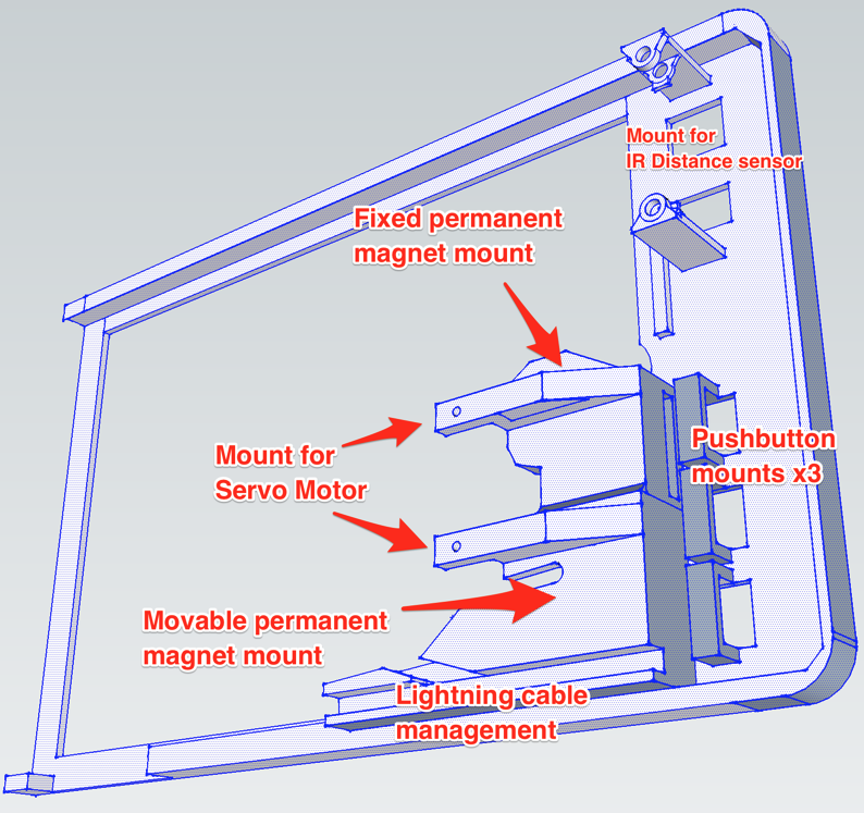
All of these solutions must, of course, be embedded in an attractive and functional mount that actually holds the iPad and the components necessary to interact with the iPad (e.g., cable management, mounting the distance sensor, servo, magnets, and buttons, etc.). I designed this part in Sketchup and 3D-printed it using Shapeways’ service. My mount focuses on the bottom-left corner of the mount so that it fits inside of a 18cm x 10cm x 2cm bounding box which accelerates the speed of delivery from Shapeways and reduces its cost during prototyping.
Parts List (BOM) for the Wall Mount
My Custom 3D Printable iPad Mini Mount Frame
Price: ~$50 to print in strong and flexible plastic from Shapeways
Price: $39
Price: $28
Price: $20
Price: $24
Price: $17
Price: $19
(optional if you need contact-closures for the buttons - $30)
Price: $4
Price: $16
Price: $4
Price: $12 each = $24
Price: $8 for 25 (so <$1 for the two you need)
Price: $6 for 20 (so $1.20 for the four you need)
Price: $5
Thin paperclip, glue, 22 gauge solid patch wire, RCA audio cable
Sketchup Model
Front View:

Back View:
The Circuit
Using a Particle Photon microcontroller, the circuit is straightforward. We wire D1, D2, D3, and D4 to the momentary contacts (i.e., the pushbuttons). We wire the IR distance sensor to analog input A0. Finally, we wire the pulse output for the servo motor from analog output A4, one of the pins that supports PWM output and the servo API. See the Breadboard and circuit views that I drew using Fritzing.
Breadboard View 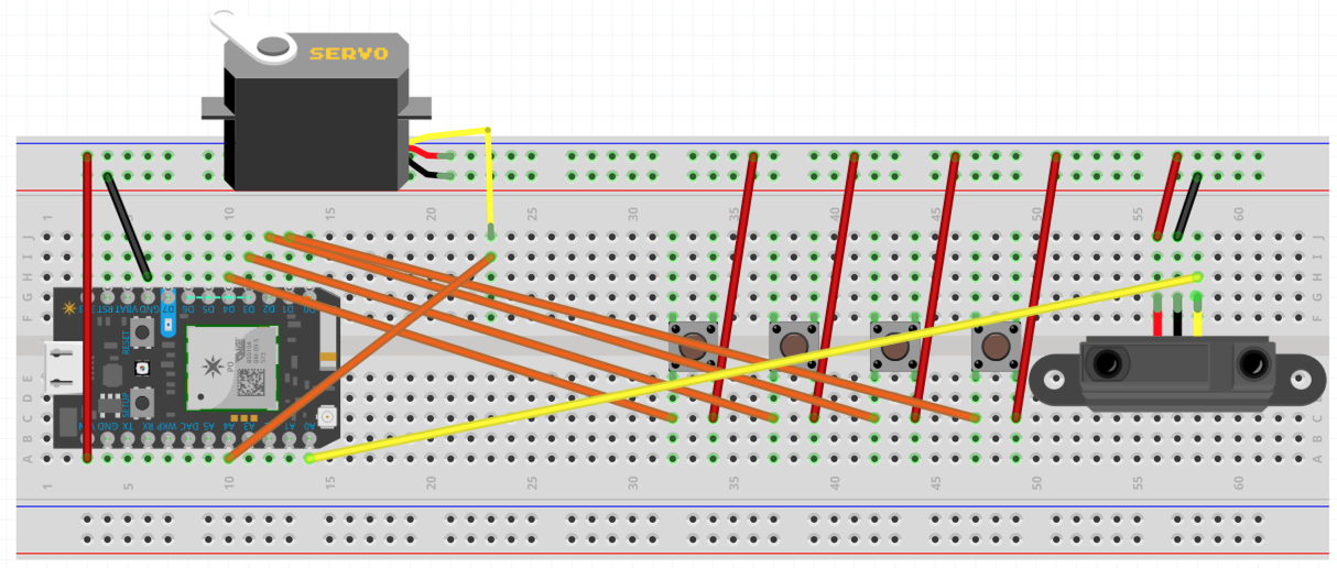
Schematic View

Assembly Instructions
After printing out the 3D model, assembly is a simple matter and takes about 30-40 minutes (probably allocated 2-3x for this the first time you try):
- Attach the servo bar to the top of the servo, bend a small paperclip into a right angle and attach it to the servo (see the finished prototype photos).
- Push the four pushbuttons through the opening in the mount and glue the bottoms of the buttons to mount.
- Solder the buttons to the power and D1 through D4 (note that the prototype photos only show one button soldered -- I didn’t bother connecting all 4 when I took the photo).
- Assemble a mini breadboard with the circuit including the Particle Photon microcontroller and connect the IR sensor and the servo wires to the breadboard.
- Connect the lightning port of the iPad to a digital camera adapter (use a lightning extension cable if you prefer). Plug another lightning cable into the digital camera adapter to power the adapter (and charge the iPad Mini), plug the other end into the 4-port powered hub.
- Plug the digital audio USB adapter into the hub, connect the S/PDIF output of the adapter to the appropriate wires on the RJ45 screw connector.
- Plug the Apple USB ethernet adapter into the hub, and plug a networking ethernet cable into the RJ45 jack on the USB ethernet adapter (the other end goes in your networking router/switch).
- Connect the +5V and GND power wires from the RJ45 screw connector to the power connectors on the powered USB hub and also to the + and - on the breadboard.
- Glue the one fixed magnet into the upper/higher magnet location in the mount, put the second, moving, magnet into the lower magnet location where it can slide around and put the other end of the paperclip through the hole from the back of the mount.
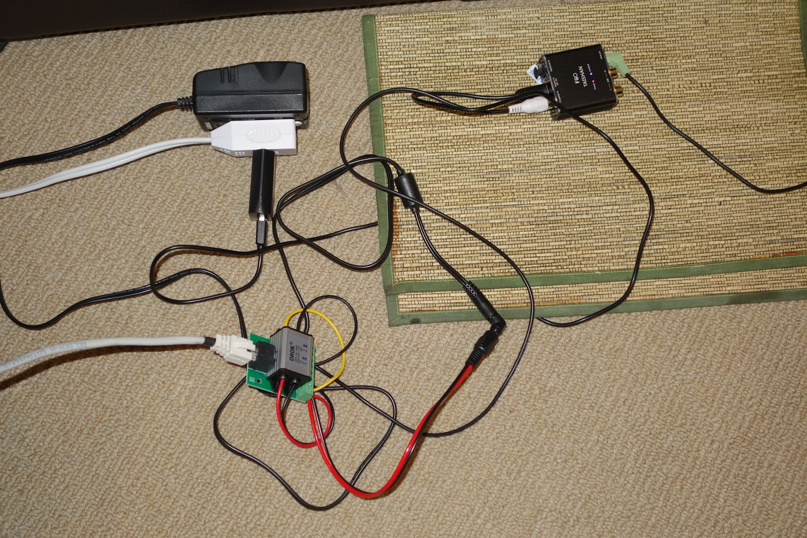
Early Prototype Photos


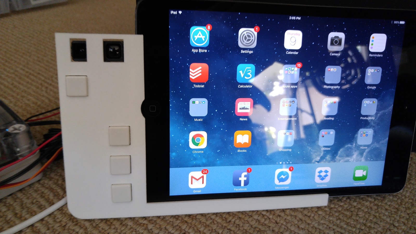
Finished Prototype Photos and Video


Alternative Designs
In this section I explain a couple alternative approaches that I considered and either discarded or might explore further.
Turning on the iPad screen
My first design used an electromagnet that either is activated (to turn the display off) or deactivated (to turn the display on) instead of a permanent magnet moved by a servo. The flaw with that design is that the solenoid required about 2 watts of power from behind the tablet to trigger its magnetic sensor. Drawing 2 watts in order to keep a display turned off seems unacceptable, hence the newer design using two permanent magnets and a servo.
Another alternative design worth exploring further is simply interrupting the charging current to the iPad and then reinstating it. iPads appear to turn on their display when plugged in, so this is also an easy solution to turning the screen on. However, the screen won’t turn off until it times out per your display settings. This approach may work well with a short timeout for turning the display off.
Sensing a User in front of the screen
I didn’t explore the alternatives for this much in designing this iPad mount because I had some experience with different approaches from an earlier project where I designed and built a directional motion sensor for counting the number of people in a room with a single doorway for entry and exit.
The sensor choices worthy of contemplating are: 1) Passive infrared (PIR); 2) Ultrasonic; and 3) IR Laser.
The sensor choices worthy of contemplating are: 1) Passive infrared (PIR); 2) Ultrasonic; and 3) IR Laser.
The disadvantage of PIR is that it’s hard to tune distance and far away larger heat footprints look identical to smaller up-close heat masses. PIR is great for its low power and completely passive nature. Note that for Android tablets, it’s possible to configure a motion detection application that uses the (visual spectrum) front-facing camera and then uses Tasker to turn on the display. Apple’s more limited power-user API precludes this approach. Using simple motion detection on the camera is flawed in similar ways to PIR, but a more heavyweight facial-recognizer would likely reduce false positives (at the expense of computational and energy expense.
Ultrasonic has a number of great properties including wider visibility and accurate distance measurement, but depending on the frequency, the sound may bother pets and more importantly, multiple uncoordinated ultrasonic sensors within earshot results in bad readings. See the Ultrasonic Doorjamb for more of a discussion of this issue (which I only found after doing my doorjamb sensor that I ultimately switched to using IR laser).
Those shortcomings ultimately led me to use an IR laser sensor. One downside that is rumored that I’ve not encountered is the worry that it can confuse IR receivers on electronics and interfere with IR cameras.
Next Steps
I’d love to see a consumer electronics company pick up on some of these ideas and make a powerful and flexible wall mount using these ideas. I’m happy to be contacted by folks interested in productionizing this.
I’m still slightly partial to tablet-stands for tablets and may turn this more into a tablet-stand to place in a wired display shelf rather than mounted on the wall.
If the push buttons on the mount are not of interest or do not need to be labelled, the mount could shrink horizontally by mounting the distance sensor vertically and using a right-angle Lightning connector. In particular, that would be easier if making a full-height frame which would allow more vertically room for the sensor. (Thanks to Eric Badros for that observation.)
2 comments:
great work man this is such an inspiring blog the way you explained deeply about the iPad is really good i think so you are an engineer. its a helpful topic for engineering students to take help for their assignment but for me i have do my assignment service from where i can get the best help i need.
Home automation may be made much easier with a feature-rich iPad wall mount that keeps controls organized and easily accessible. Similar to how London Proofreading Helpers guarantee accuracy and clarity in writing, a well-designed mount adds efficiency and order to everyday tasks, making technology feel natural and improving convenience and the whole home experience.
Post a Comment